
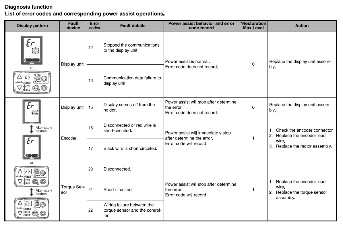
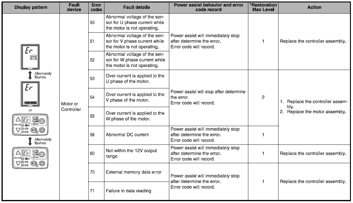
Yamaha error codes. Troubleshooting

Yamaha Error Codes & Fixes PW and PWSE drive units


Fault diagnostic mode Yamaha 950 midnight Star 2011


Yamaha YZF-R125 Service Manual: Self-diagnostic function table


Access to diagnostics.
- Turn off the ignition, leave the stop / start button in the OFF position
- Press the RESET and SELECT buttons on the dashboard
- Turn on the ignition without releasing the button, wait about eight seconds until DIAG appears on the dashboard. Release the buttons
At this stage, you can switch between testing and setting CO by holding the SELECT button for a couple of seconds.
- Next, in DIAG mode, hold down the RESET and SELECT buttons for a couple of seconds and voila! test before you
Attention! do not switch between tests when the start stop button is ON. This button in testing is responsible for starting the test, and should only be turned ON if you want to run a test.
Testing:
The RESET and SELECT buttons can be used to switch between tests. The general meaning of the test is the same for all equipment, but some of the nuances of the test, namely the value of the sensor readings (for example, the percentage of the throttle position angle) - may vary - check the data in the service manuals of your equipment
To run the test you want, move the engine start switch to the ON position
|
Error code |
Sensor |
Symptom |
launch |
riding |
Self-diagnosis code |
measurements |
Indications |
|
12 |
crankshaft sensor |
crankshaft sensor signal |
No |
No |
_ |
|
|
|
13 |
inlet air pressure sensor No. 1 (1, 2 and 3 cylinders) |
open or short circuit |
Yes |
Yes |
d:03 |
pressure measurement of incoming and atmospheric air |
atmospheric pressure or less than atmospheric |
|
fourteen |
inlet air pressure sensor No. 1 (1, 2 and 3 cylinders) |
hose system malfunction (clogged or disconnected) |
Yes |
Yes |
d:03 |
pressure measurement of incoming and atmospheric air |
atmospheric pressure or less than atmospheric |
|
fifteen |
throttle position sensor |
open or short circuit |
Yes |
Yes |
d:01 |
throttle angle |
0-125 (15-18 fully open 94-100 fully closed) |
|
16 |
throttle position sensor |
throttle stuck |
Yes |
Yes |
d:01 |
throttle angle |
0-125 (15-18 fully open 94-100 fully closed) |
|
21 |
coolant temperature sensor |
open or short circuit |
Yes |
Yes |
d:06 |
coolant temperature measurement |
minimum value -30 |
|
22 |
inlet air temperature sensor |
open or short circuit |
Yes |
Yes |
d:05 |
measurement of air temperature in the air filter |
minimum value -30 |
|
25 |
inlet air pressure sensor No. 2 (1 cylinder) |
open or short circuit |
Yes |
Yes |
d:04 |
pressure measurement of incoming and atmospheric air |
atmospheric pressure or less than atmospheric |
|
26 |
inlet air pressure sensor No. 2 (1 cylinder) |
hose system malfunction (clogged or disconnected) |
Yes |
Yes |
d:04 |
pressure measurement of incoming and atmospheric air |
atmospheric pressure or less than atmospheric |
|
thirty |
oil pressure drop |
engine will stop when pressure drop is detected |
No |
No |
_ |
|
|
|
33 |
ignition coil (1 cylinder) |
ignition coil primary wire |
depending on the number of non-working cylinders |
depending on the number of non-working cylinders |
d:30 |
ignition spark test |
after switching on, there will be 5 sparks on the candle and a flashing lamp will blink 5 times |
|
34 |
ignition coil (2 cylinder) |
ignition coil primary wire |
depending on the number of non-working cylinders |
depending on the number of non-working cylinders |
d:31 |
ignition spark test |
after switching on, there will be 5 sparks on the candle and a flashing lamp will blink 5 times |
|
35 |
ignition coil (3 cylinder) |
ignition coil primary wire |
depending on the number of non-working cylinders |
depending on the number of non-working cylinders |
d:32 |
ignition spark test |
after switching on, there will be 5 sparks on the candle and a flashing lamp will blink 5 times |
|
37 |
idle control valve |
high idle engine speed |
yes (no if the valve is stuck in the closed position) |
Yes |
d:54 |
idle valve control |
|
|
42 |
speed sensor |
abnormal sensor signal |
Yes |
Yes |
d:07 |
pulse velocity measurement |
0-999 (after 999 reset to 0) is it normal for numbers to appear in order? |
|
43 |
fuel system voltage |
power supply for fuel injectors and fuel pump |
depending on conditions |
depending on conditions |
d:09 |
fuel system supply voltage measurement |
0-18.7V normal - 12 |
|
44 |
CO level control error |
CO level error detected |
Yes |
Yes |
d:60 |
|
shows the number of the faulty cylinder |
|
46 |
snowmobile power supply error (voltage monitoring) |
ECU (computer) power is abnormal |
Yes |
Yes |
_ |
|
|
|
fifty |
ECU memory error |
computer error |
No |
No |
_ |
|
|
|
81 |
heated handles |
open or short circuit |
Yes |
Yes |
d:57 |
handle heating check |
|
|
83 |
gas trigger heating |
open or short circuit |
Yes |
Yes |
d:27 |
checking gas trigger heating |
|
|
84 |
TORS |
malfunction of the emergency engine blocking system |
Yes |
No |
d:01 |
throttle angle |
0-125 (15-18 fully open 94-100 fully closed) |
|
d:07 |
pulse velocity measurement |
0-999 (after 999 reset to 0) is it normal for numbers to appear in order? |
|||||
|
d:24 |
throttle sensor position |
on - open off - closed |
|
85 |
oil pressure sensor |
open circuit |
Yes |
Yes |
_ |
|
|
|
ER-1 |
internal ECU malfunction |
no signal from computer |
No |
No |
_ |
|
|
|
ER-2 |
internal ECU malfunction |
no signal from the computer for the specified time |
No |
No |
_ |
|
|
|
ER-3 |
internal ECU malfunction |
data from computer is not correct |
No |
No |
_ |
|
|
|
ER-4 |
internal ECU malfunction |
data is not received from the measuring device |
No |
No |
_ |
|
|
|
|
|
|
|
|
d:36 d:37 d:38 |
check 1, 2 and 3 injectors |
after turning on, the injector will work 5 times (checked by ear) |
|
|
|
|
|
|
d:50 |
injection system check |
after switching on, the injectors will work 5 times (verified by ear) |
|
|
|
|
|
|
d:52 |
checking lighting fixtures |
includes lighting fixtures |
|
|
|
|
|
|
d:59 |
Passenger grip heating test |
|
|
|
|
|
|
|
d:61 |
error history |
shows error codes 12-85 |
|
|
|
|
|
|
d:62 |
erasing error history |
shows number of errors 00-23 |
|
|
|
|
|
|
d:70 |
program control code |
00-255 |