
Chevrolet Cruze Fuse and Relay Diagram
Fuse and relay boxes in the engine compartment
The main part of the fuse elements on the Chevrolet Cruze is located in the engine compartment.
Depending on the modifications, there are only three blocks that are responsible for different parts of the electronic circuit of the vehicle.
It is prohibited to change the fuse rating to a higher one or insert it into the jumper socket - this can cause a wiring fire, leading to irreversible consequences.
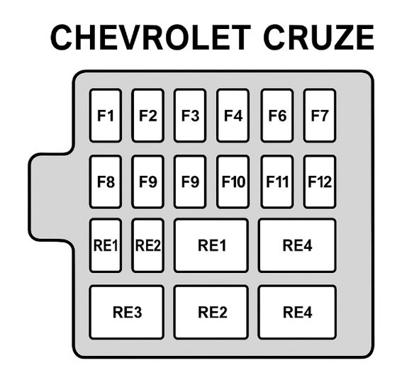
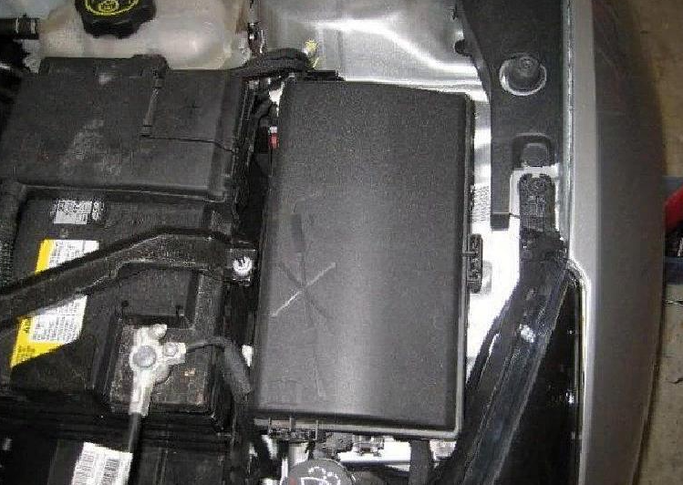
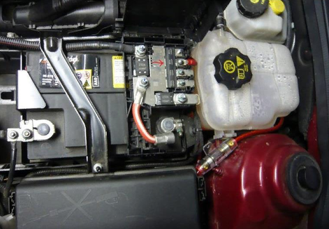
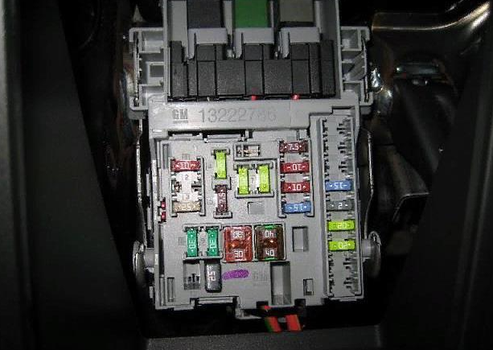
Main block with relays and fuses
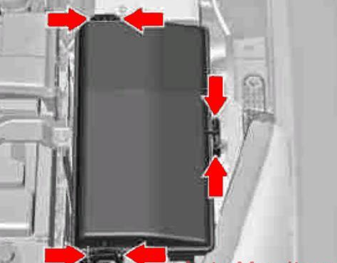
The main fuse block of the Chevrolet Cruze is located in the space between the battery and the left wing. You can find it by the square plastic cover, closed with three latches.
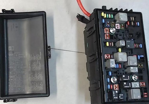
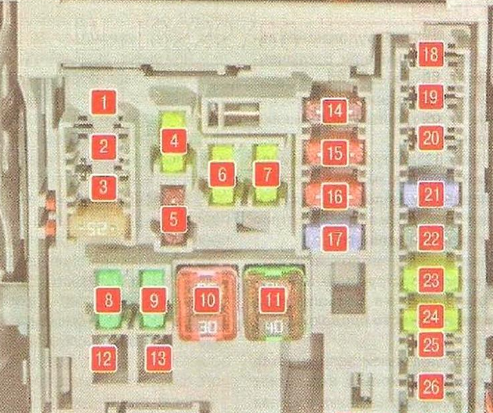
Opening the protective panel reveals a full set of fuses
The reverse side of the unit shows a diagram of the location of the fuses and relays. There are also special tweezers to facilitate the removal and replacement procedure.
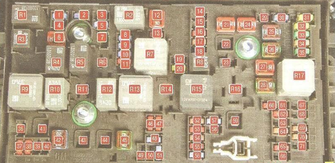
Fuse
№ What is responsible for. Power, A
1 Gearbox control unit 15
2 Engine control unit 15
3 Not used —
4 Evaporative canister solenoid valve 10
5 Ignition 15
6 Windscreen wiper 30
7 Not used —
8 Fuel injection system 15
9 Fuel injection system, ignition system 15
10 Engine control unit 15
11 Oxygen concentration sensor 10
12 Starter solenoid relay 30
13 Evaporative canister solenoid valve 7.5
14 Not used —
15 Rear window wiper 20
16 Ignition, air quality sensor (air conditioning system) 7.5
17 Ignition, airbag 5
18 Throttle position sensor 10
19 Not used —
20 Fuel pump 20
21 Rear electric windows 30
22 Not used used —
23 Not used —
24 Front electric windows 30
25 Electronically controlled vacuum pump 20
26 ABS 40
27 Smart key control system 30
28 Rear window defroster 40
29 Not used —
30 ABS 15
31 Body control module 20
32 Body control module 20
33 Heated front seats 30
34 Sunroof 25
35 Audio system 30
36 Not used —
37 Right high and low beam headlight 10
38 Left high and low beam headlight 10
39 Not used —
40 Not used —
41 Not used —
42 Engine cooling fan 40/ 30/ 20
43 Not used —
44 Not used —
45 Engine cooling fan 40
46 Cooling fan 10
47 Oxygen sensor 10
48 Fog lights 15
49 Not used —
50 Not used —
51 Horn 15
52 Instrument cluster 15
53 Electric mirror 10
54 Light switch, light control 5
55 Mirror folding 7.5
56 Windscreen washer 15
57 Steering column lock 15
58 Not used —
59 Diesel fuel heater 30
60 Mirror defroster 7.5
61 Mirror defroster 7.5
62 Air quality 10
63 Rear window sensor 7.5
64 Air quality sensor 5
65 Rear fog lights 7.5
66 Rear window washer 15
67 Fuel control unit 20
68 Not used —
69 Battery voltage sensor 5
70 Rain sensor 5
71 Not used —
Relay
R1 Air conditioning compressor drive clutch
R2 Starter solenoid relay
R3 Engine cooling fan (K7)
R4 Front windshield wiper mode (speed) relay
R5 Front windshield wipers
R6 Not used
R7 Engine management system main relay
R8 Fuel pump
R9 Engine cooling fan (K2)
R10 Engine cooling fan (K3)
R11 Not used
R12 Engine cooling fan (K3)
R13 Engine cooling fan (K1)
R14 Not used
R15 Ignition
R16 Pre-heating system (diesel)
R17 Heated outside rear-view mirrors
High Power Fuse Block
This unit is located on the battery cover and serves to protect particularly loaded units.
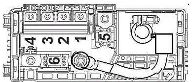
1 Instrument cluster 100 A
2 Instrument cluster 100 A
3 Electric power steering drive 80 A
4 Not used -
5 Additional fuse bank 250 A
6 Starter motor 250/500 A
Additional relay block
The third assembly block is located next to the main units and is auxiliary. The presence of the unit is conditional and depends on the configuration; the panel may be absent from the vehicle design.
1 Infotainment system, telephone with reduced volume 10A
2 Not used —
3 Body control module 25A
4 Infotainment system 20A
5 Information display, parking assistance 7.5A
6 Fuse for cigarette lighter 20A
7 Socket 20A
8 Body control module 30A
9 Body control module 30A
14 Diagnostic socket 5A
15 Airbag 10A
16 Central locking, rear tailgate 10A
17 Air conditioning 15A
18 Not used —
19 Gear lever 5A
20 Not used —
21 Instruments 15A
22 Ignition, smart key system 2A
23 Body control module 20A
24 Body control module 20A
25 Steering column lock 20A
26 Not used —
Removal and replacement process
There are cases when after replacing a certain element the breakdown is not solved. Even after a complete service of the supposed place of dysfunction, the malfunction remains. In this case, the manufacturer recommends paying attention to the seat itself.
There are often moments when the main part is completely serviceable, there are no short circuits in the wiring, but the car still behaves inadequately. In this case, further diagnostics acquire radical methods. We are talking about a complete replacement of the fuse box with a known good one, or, in other words, a new one. The reason is the burnout of the tracks.
Replacing the underhood fuse box
To replace the underhood fuse box, you need to perform the following sequence of actions.
- Disconnect the positive battery terminal.
- Use a 10 mm wrench to unscrew the three panel fixing bolts.
- Use a flat-head screwdriver or similar tool to pry up the mounting terminals.
- Remove the unit from its seat.
- Unscrew the bundle of wires from the end.
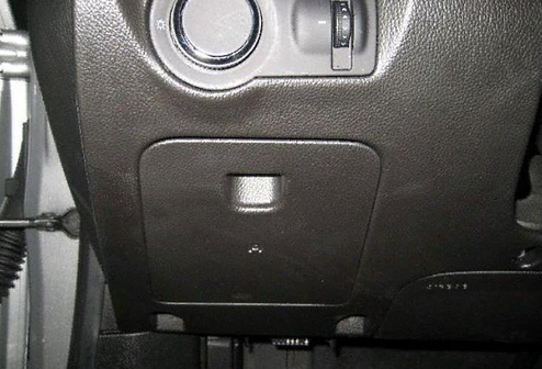
Replacing the cabin fuse box
For the cabin part, the sequence of actions is as follows:
- Disconnect the power supply to the battery.
- Remove the lower part of the instrument panel.
- Disconnect the wiring block from the element.
- Then you need to pull the unit up and towards you.